If you want to connect to ALOM from an external PC or terminal using a modem, you can connect an external modem to the serial management port (SERIAL MGT). This allows you to run the ALOM software using your remote PC.
However, you can only use the modem for incoming ASCII connections to connect to the serial port to obtain the ALOM command prompt (sc>). Outgoing calls from ALOM using a modem are not supported.
Before attaching the modem to the serial management port, set the modem to factory default settings. On many modems, setting the factory default settings is done by using the AT&F0 command.
In order to connect the modem to the serial management port, a specific connector needs to be created or purchased with the specific pinout requirements.
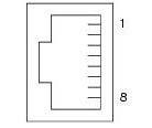
The following illustration and table includes information about pin assignments and signal descriptions that are relevant to an RJ-45 connector. The following illustration is an example of an RJ-45 jack.
The following illustration and table include information about the serial port connector and signals that are relevant to a DB-25 connector. The following illustration is an example of a DB-25 female connector.
| Pin Number | Function | I/O | Signal Description |
|---|---|---|---|
| 1 | none | none | N.C.* |
| 2 | TXD_A | O | Transmit Data |
| 3 | RXD_A | I | Receive Data |
| 4 | RTS_A | O | Ready To Send |
| 5 | CTS_A | I | Clear To Send |
| 6 | DSR_A | I | Data Set Ready |
| 7 | GND | Signal Ground | |
| 8 | DCD_A | I | Data Carrier Detect |
| 9 | none | none | N.C.* |
| 10 | none | none | N.C.* |
| 11 | DTR_B | O | Data Terminal Ready |
| 12 | DCD_B | I | Data Carrier Detect |
| 13 | CTS_B | I | Clear To Send |
| 14 | TXD_B | O | Transmit Data |
| 15 | TRXC_A | I | Transmit Clock |
| 16 | RXD_B | I | Receive Data |
| 17 | RXC_A | I | Receive Clock |
| 18 | RXC_B | I | Receive Clock |
| 19 | RTS_B | O | Ready To Send |
| 20 | DTR_A | O | Data Terminal Ready |
| 21 | none | none | N.C.* |
| 22 | none | none | N.C.* |
| 23 | none | none | N.C.* |
| 24 | TXC_A | O | Transmit Clock |
| 25 | TXC_B | O | Transmit Clock |
* N.C. means "No Connection."
One way to connect a modem to this port is to use a modified RJ-45 to DB-25 connector, Sun part number 530-2889-03, and a crossover RJ-45 to RJ-45 cable. The connector 530-2889-03 is modified by extracting the DB-25 pin in the pin 6 position and inserting it into the pin 8 position.
If you want to connect wiring yourself, translate the signals between the RJ-45 and DB-25 connectors according to the following information.
| RJ-45 | DB-25 |
1 - RTS |
5 - CTS |
2 - DTR |
6 - DSR |
3- TXD |
3 - RXD |
4 - GND |
7 - GND |
5 - RXD |
7 - GND |
6 - RXD |
2 - TXD |
7 - DCD |
8 - DCD |
8 - CTS |
4 - RTS |
| Issue | Solution |
| ALOM modem does not answer | Verify that cabling is set up correctly. See the if_modem variable for additional information. |
| ALOM modem answers then immediately hangs up | Verify that the if_modem variable is set to true. |
| ALOM modem answers but connections appear dead |
|